Home > Load Cells > TC4
TC4
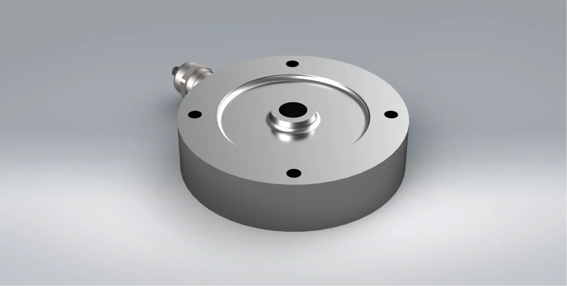
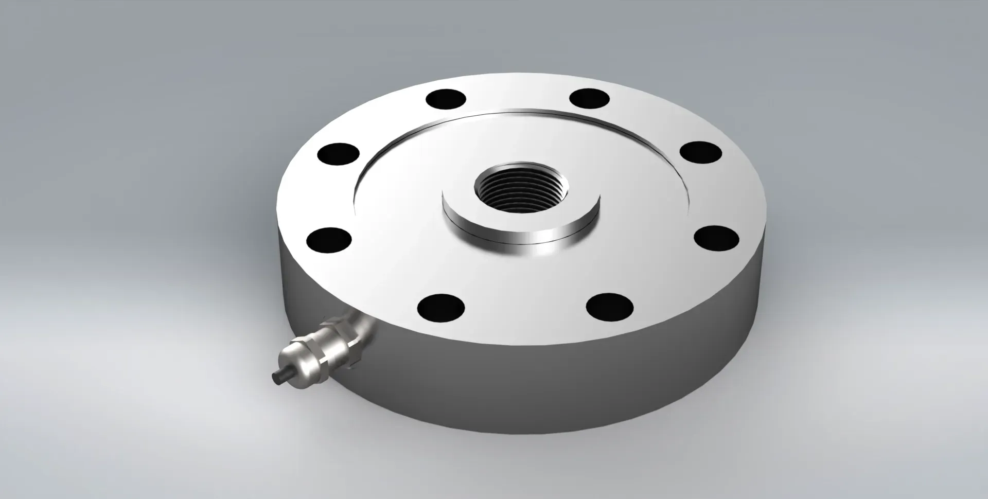
Bi-Directional Pancake Load Cell
CAPACITY
250KG – 500TF
NON-LINEARITY
0.05%RO
RATING
IP67
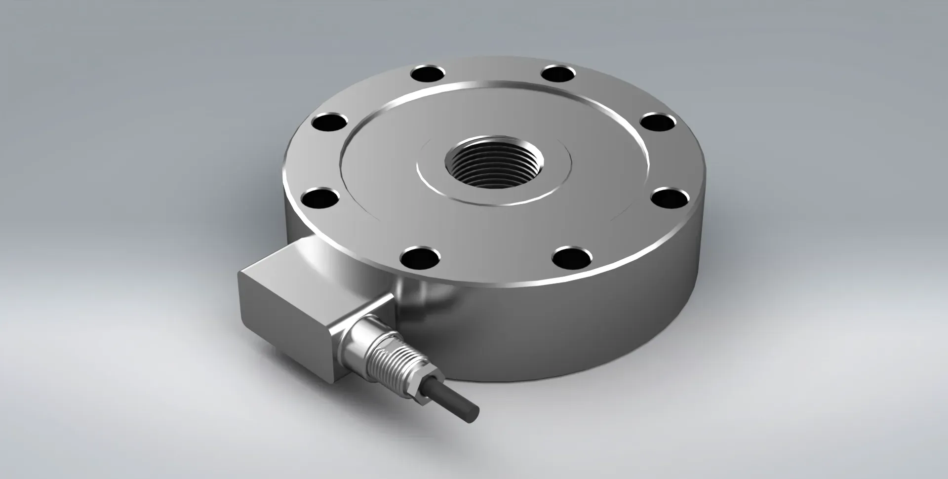
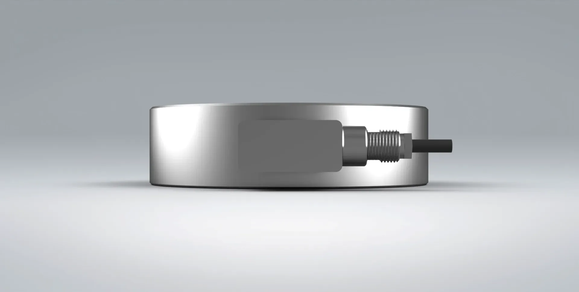
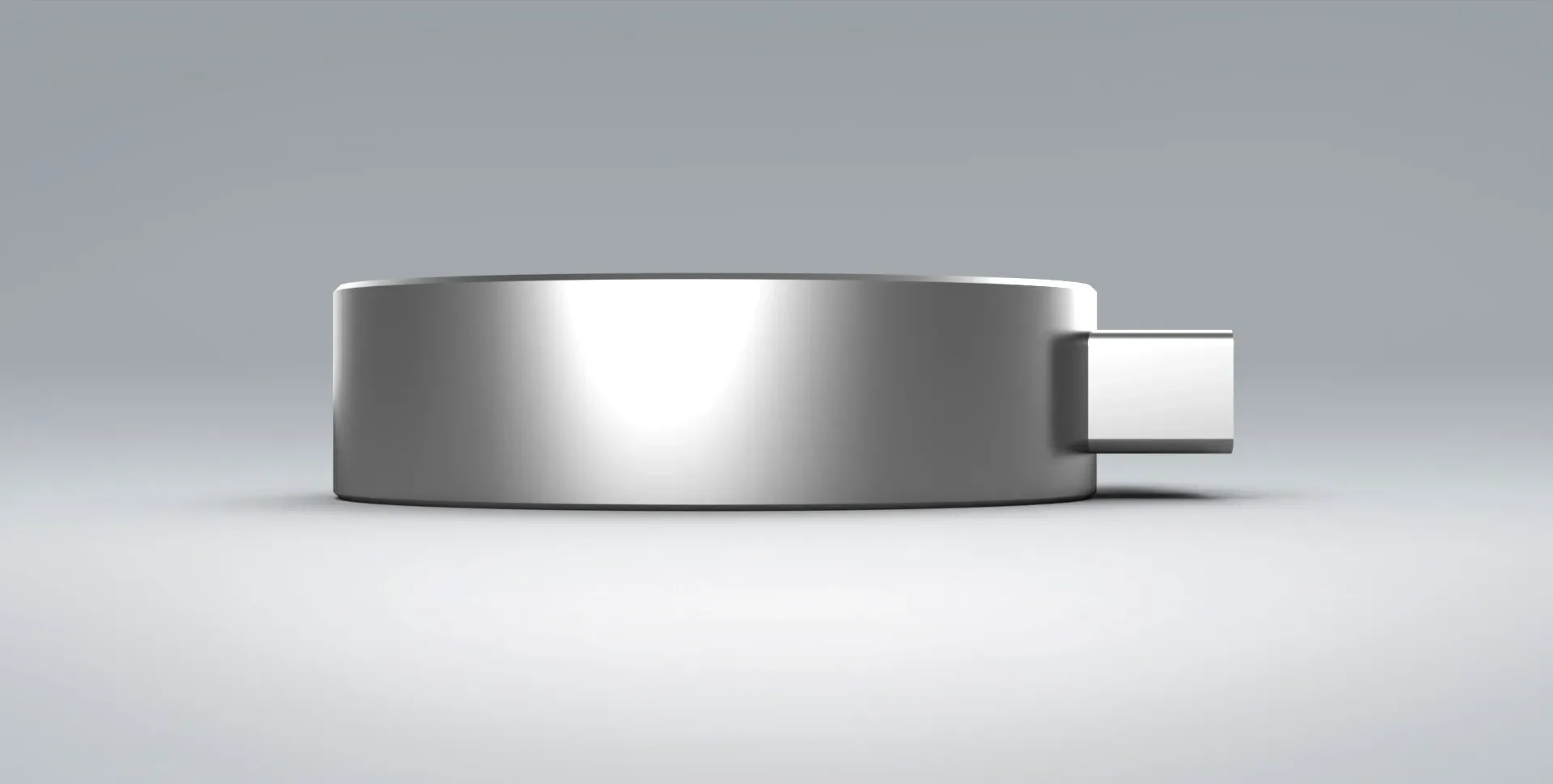
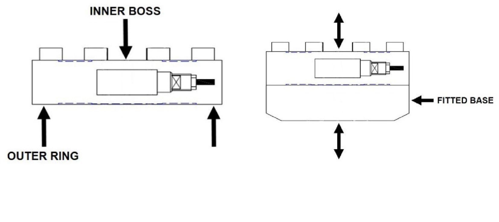
The TC4 bi-directional pancake load cell is a low-profile device for tension and compression measurement during static or dynamic testing.
With a fully laser welded, stainless steel assembly, the TC4 load cell offers high resilience to wear and tear, as well as IP67 sealing.
In addition, the TC4 is rated to ISO 376 Class 1, making it ideally suited for test rig applications.
For the full product specification and a complete list of options/accessories available, please download the product datasheet.
Should the TC4 not quite suit your requirement, the PLC load cell may be of interest, as its design can be customised – please refer to the PLC datasheet for more information.
To view the full specification, please download the product datasheet.
Similar Products
Typical Specification
| PARAMETER | VALUE | UNITS |
|---|---|---|
| Capacities Range | 0.25(1), 0.5, 1, 2.5, 5, 10, 20, 30, 50, 75, 100, 200, 300(2), 500(2) | tf |
| Rated Output | 2(3) | mV/V |
| Sensitivity Tolerance | 0.1 | ±% of Rated Output |
| Relative Error (REPEATABILITY 0°-120°-240° (b)) | 0.145(4) | ±% of Rated Output |
| Relative Error (INTERPOLATION (fc)) | 0.090(4) | ±% of Rated Output |
| Relative Error (REVERSIBILITY (u)) | 0.240(4) | ±% of Rated Output |
| Relative Error (ZERO (fo)) | 0.030 | ±% of Rated Output |
| Linearity & Hysteresis | 0.05 | ±% of Rated Output |
| Temperature Effect (ON ZERO) | 0.028 | ±% of Rated Output/°C |
| Temperature Effect (ON OUTPUT) | 0.024 | ±% of Rated Output/°C |
| Effect of Transverse Load | 0.030 | ±% of Rated Output |
| Input Resistance (NOMINAL LOAD) | 800±20(0.25-50tf) 430±20(>50tf) | Ω |
| Output Resistance (NOMINAL LOAD) | 705±2(0.25-50tf) 352±2(>50tf) | Ω |
| Insulation Resistance | >5 | GΩ |
| Zero Balance | ≤1 | ±% of Rated Output |
| Excitation (RECOMMENDED SUPPLY) | 10 | Volts AC or DC |
| Excitation (NOMINAL SUPPLY RANGE) | 1-15 | Volts AC or DC |
| Excitation (MAXIMUM SUPPLY) | 18 | Volts AC or DC |
| Mechanical Limit (SERVICE LOAD) | 120 | % of Rated Output |
| Mechanical Limit (SAFE OVERLOAD) | 150 | % of Rated Output |
| Mechanical Limit (ULTIMATE OVERLOAD) | 300 | % of Rated Output |
| Mechanical Limit (SAFE TRANSVERSE LOAD) | 100 | % of Rated Output |
| Mechanical Limit (SAFE DYNAMIC LOAD) | 75(5) | % of Rated Output |
| Temperature Range (OPERATING) | -10 to +70 | °C |
| Temperature (STORAGE) | -20 to +80 | °C |
| Environmental Sealing | IP67 | - |
| Cable | 5(6) | m |
| Construction Material | Stainless Steel | - |
| PARAMETER | 0.25, 0.5, 1, 2.5tf | 5, 10tf | 20, 30tf | 50tf | 75, 100tf | 200tf | 300, 500tf |
|---|---|---|---|---|---|---|---|
| Displacement at Nominal Load (mm) | ~0.06 | ~0.09 | ~0.17 | ~0.17 | ~0.23 | ~0.21 | ~0.21 |
| Weight (KG) | ~1.6 | ~2.5 | ~5.8 | ~6.8 | ~16.5 | ~35 | ~63 |
| Fixing Screw (DIAMETER) | M8 | M10 | M16 | M16 | M24 | M24 | M27 |
| Fixing Screw (RESISTANCE CLASS) | 12.9 | 12.9 | 12.9 | 12.9 | 12.9 | 12.9 | 12.9 |
| Fixing Screw (TIGHTENING TORQUE Nm) | 40 | 70 | 368 | 368 | 460 | 460 | 1500 |
(1) The 0.25tf TC4 load cell is not available with built-in amplified output. (2) The 300tf and 500tf rated TC4 load cells are guaranteed in tension up to 250tf only. (3) Tests and calibrations performed in compression with the load cell mounted on a bearing support with correctly tightened clamping screws. (4) Percentage errors referred to reading, min. 1/10 of nominal load. (5) The dynamic load must be applied to the load cell central thread and not to the external fixing rim. (6) As standard the 200-500tf rated TC4 load cells are supplied fitted with a MIL7M connector with mating 5m cable.
Additional Information
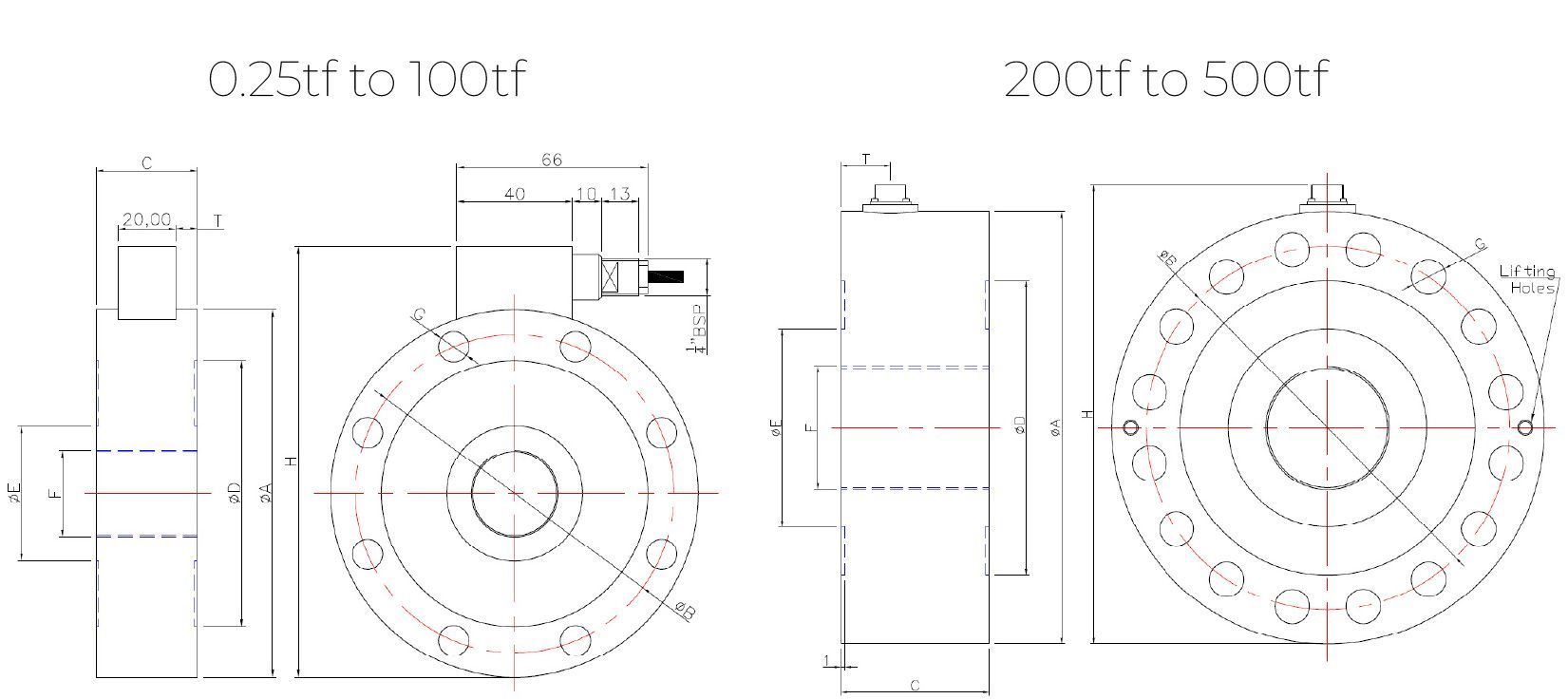
| LOAD (tf) | ORDERING CODE | ØA | B | C | ØD | ØE | F | G | № G | H | T | KHZ(5) |
|---|---|---|---|---|---|---|---|---|---|---|---|---|
| 0.25 | CTC4100250K5 | 100 | 86 | 35 | 72 | 32 | M20x1.5 | 9 | 6 | 121 | 7.5 | 2.5 |
| 0.5 | CTC4100500K5 | 100 | 86 | 35 | 72 | 32 | M20x1.5 | 9 | 6 | 121 | 7.5 | 2.5 |
| 1 | CTC41001T5 | 100 | 86 | 35 | 72 | 32 | M20x1.5 | 9 | 6 | 121 | 7.5 | 2.5 |
| 2.5 | CTC41002T55 | 100 | 86 | 35 | 72 | 32 | M20x1.5 | 9 | 6 | 121 | 7.5 | 4.8 |
| 5 | CTC41275T5 | 127 | 110 | 35 | 92 | 47 | M30x2 | 10.5 | 8 | 149 | 7.5 | 3.8 |
| 10 | CTC412710T5 | 127 | 110 | 35 | 92 | 47 | M30x2 | 10.5 | 8 | 149 | 7.5 | 5.8 |
| 20 | CTC416520T5 | 165 | 138 | 50 | 108 | 62 | M42x3 | 17 | 12 | 188 | 15 | 5.7 |
| 30 | CTC416530T5 | 165 | 138 | 50 | 108 | 62 | M42x3 | 17 | 12 | 188 | 15 | 7.3 |
| 50 | CTC416550T5 | 165 | 138 | 60 | 108 | 62 | M42x3 | 17 | 12 | 188 | 20 | 9.8 |
| 75 | CTC423075T5 | 230 | 185 | 80 | 145 | 98 | M60x3 | 25 | 12 | 254 | 30 | 3.2 |
| 100 | CTC4230100T5 | 230 | 185 | 80 | 145 | 98 | M60x3 | 25 | 12 | 254 | 30 | 3.2 |
| 200 | CTC4300200T5 | 300 | 250 | 100 | 198 | 132 | M100x3 | 25 | 16 | 339 | 50 | 2.7 |
| 300 | CTC4350300T5 | 350 | 294 | 120 | 238 | 178 | M100x3 | 28 | 16 | 389 | 60 | 2.8 |
| 500 | CTC4350500T5 | 350 | 294 | 130 | 238 | 178 | M100x3 | 28 | 16 | 389 | 65 | 2.8 |
Accessories
Below are the dimensions and ordering codes for the accessories available for the BD-TC4 load cell range. The accessories are produced from stainless steel (Rating 0.25-20tf = Rm ≥90KG/mm2 and 30-500tf = Rm ≥130KG/mm2).
WARNING: Check that the fixing screws and any accessories are correctly tightened before use.
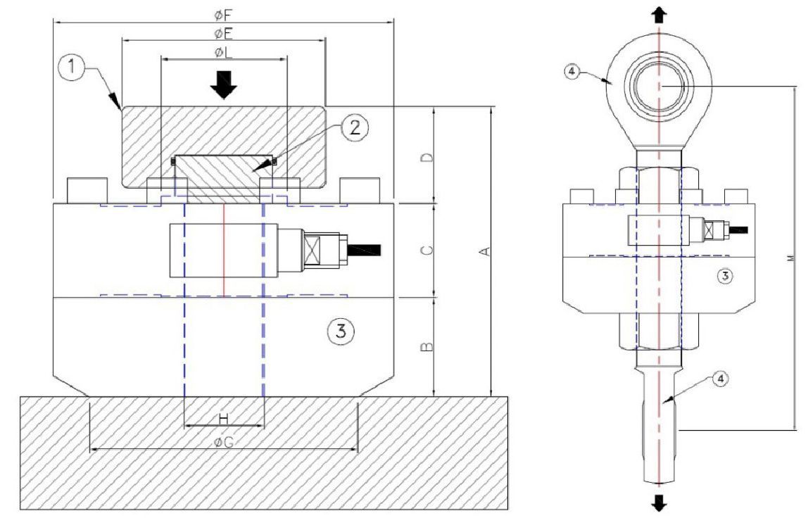
| LOAD (tf) | A | B | C | D | ØE | ØF | ØG | H | ØL | M |
|---|---|---|---|---|---|---|---|---|---|---|
| 0.25, 0.5, 1, 2.5 | 108 | 37 | 35 | 36 | 57 | 100 | 70 | M20x1.5 | 32 | ~170 |
| 5, 10 | 108 | 37 | 35 | 36 | 76 | 127 | 100 | M30x2 | 47 | ~200 |
| 20 | 169 | 60 | 50 | 59 | 76 | 165 | 100 | M42x3 | 62 | ~224 |
| 30 | 169 | 60 | 50 | 59 | 76 | 165 | 100 | M42x3 | 62 | ~465 |
| 50 | 179 | 60 | 60 | 59 | 76 | 165 | 100 | M42x3 | 62 | ~513 |
| 75, 100 | 252 | 85 | 80 | 87 | 126 | 230 | 180 | M60x3 | 98 | - |
| 200 | 309 | 85 | 100 | 124 | 129 | 300 | 250 | M100x3 | 132 | - |
| 300 | 384 | 120 | 120 | 144 | 168 | 350 | 330 | M100x3 | 178 | - |
| 500 | 394 | 120 | 130 | 144 | 168 | 350 | 330 | M100x3 | 178 | - |
| LOAD (tf) | ORDERING CODE | ACCESSORY DESCRIPTION |
|---|---|---|
| 0.25, 0.5, 1, 2.5 | CTIC22 | (1)Loading Head |
| 0.25, 0.5, 1, 2.5 | CTC425M20 | (2)Spherical Loading Head (M20x1.5) |
| 0.25, 0.5, 1, 2.5 | CPBTC4D100 | (3)Mounting Plate (Ø100mm) |
| 0.25, 0.5, 1, 2.5 | CACCEM20 | (4)Knuckle Joints |
| 5, 10 | CTIC28 | (1)Loading Head |
| 5, 10 | CTC445M30 | (2)Spherical Loading Head (M30x2) |
| 5, 10 | CPBTC4D127 | (3)Mounting Plate (Ø127mm) |
| 5, 10 | CACCEM30 | (4)Knuckle Joints |
| 20, 30, 50 | CTIC35 | (1)Loading Head |
| 20, 30, 50 | CTS62M42 | (2)Spherical Loading Head (M42x3) (20-30tf) |
| 20, 30, 50 | CTC450M42 | (2)Spherical Loading Head (M42x3) (50tf) |
| 20, 30, 50 | CPBTC4D165 | (3)Mounting Plate (Ø165mm) |
| 20, 30, 50 | CACCEM42 | (4)Knuckle Joints (20tf) |
| 20, 30, 50 | CACCEM4230T | (4)Knuckle Joints (30tf) |
| 20, 30, 50 | CACCEM4250T | (4)Knuckle Joints (50tf) |
| 75, 100 | CTIC60 | (1)Loading Head |
| 75, 100 | CTS96M60 | (2)Spherical Loading Head (M60x3) |
| 75, 100 | CPBTC4D230 | (3)Mounting Plate (Ø230mm) |
| 200 | CTIC106 | (1)Loading Head |
| 200 | CTS160M100 | (2)Spherical Loading Head (M100x3) (200tf) |
| 200 | CPBTC4D300 | (3)Mounting Plate (Ø300mm) |
| 300, 500 | CTIC140 | (1)Loading Head |
| 300, 500 | CTS170M100 | (2)Spherical Loading Head (M100x3) (300-500tf) |
| 300, 500 | CPBTC4D350 | (3)Mounting Plate (Ø350mm) |
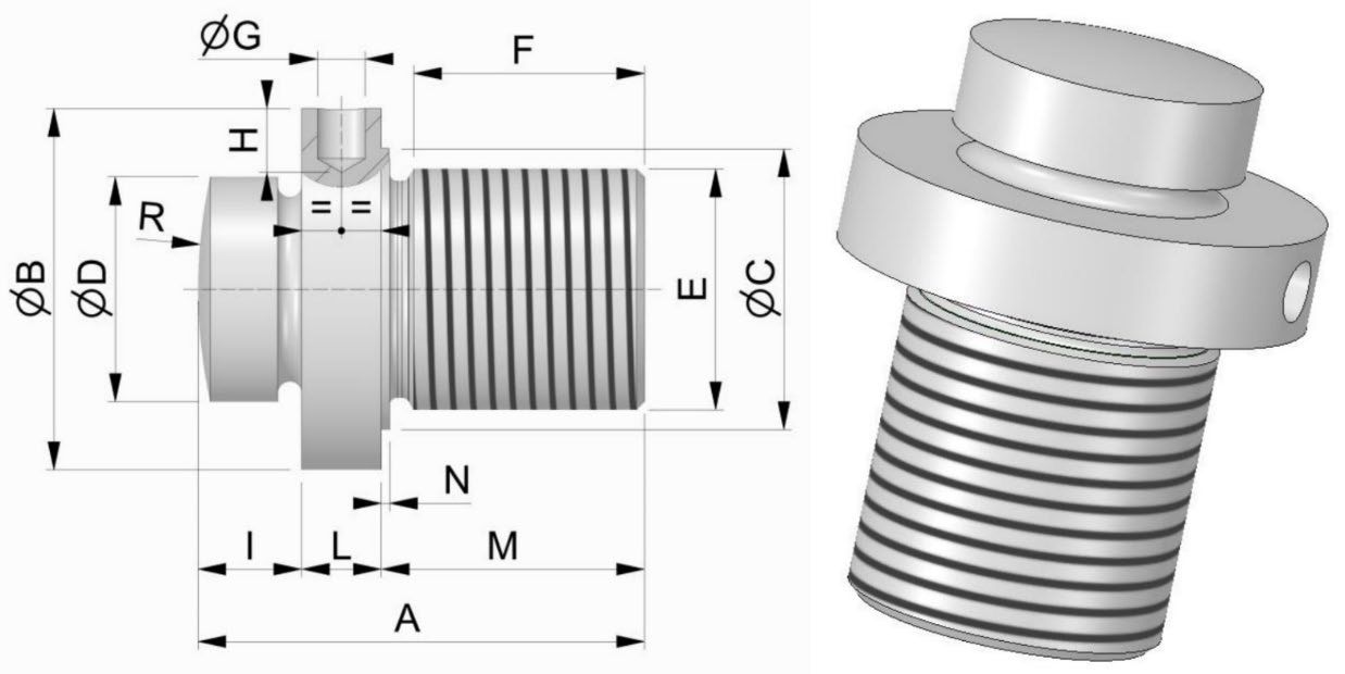
| CODE | A | ØB | ØC | ØD | E | F | ØG | H | I | L | M | N | R |
|---|---|---|---|---|---|---|---|---|---|---|---|---|---|
| CTC425M20 | 54 | 32 | 25 | 22 | M20x1.5 | 29 | 5 | 6 | 12 | 9 | 33 | 1 | R45 |
| CTC445M30 | 56 | 45 | 35 | 28 | M30x2 | 29 | 6 | 8 | 13 | 10 | 33 | 1 | R65 |
| CTS62M42 | 87 | 60 | 50 | 35 | M42x3 | 39 | 6 | 10 | 16 | 25 | 46 | 1 | R160 |
| CTC450M42 | 97 | 60 | 50 | 35 | M42x3 | 49 | 6 | 10 | 16 | 25 | 56 | 1 | R160 |
| CTS96M60 | 140 | 96 | - | 60 | M60x3 | 75 | 6 | 8 | 15 | 47 | 78 | - | R220 |
| CTS160M100 | 160 | 127 | 120 | 106 | M100x3 | 92 | 8 | 15 | 30 | 30 | 100 | 2 | R350 |
| CTS170M100 | 184 | 165 | 160 | 140 | M100x3 | 112 | 12 | 20 | 34 | 30 | 120 | 2 | R500 |
Connector Options
| ORDERING CODE | DESCRIPTION |
|---|---|
| CMIL6MF + CMIL6FV5 | Direct MIL6M output connector. Female 6 poles straight MIL6M connector complete with 5m PVC shielded cable. |
| CONNM12MF + CONNM12FV5 | Direct M12 output connector. Female 5 poles straight M12x1 connector complete with 3m PVC shielded cable. |
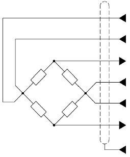
Wiring Details
As standard the 200-500tf rated TC4 load cells are supplied fitted with MIL7M connector with mating 5m cable.
PVC 105°C shielded cable, Ø 5.2mm with 4× Ø 0.35mm2 tinned conductors. Shield connected to the body of the transducer
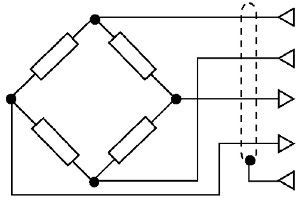
| OUTPUT | CABLE (STANDARD) | MIL6M (OPTIONAL) | M12 (OPTIONAL) |
|---|---|---|---|
| EXCITATION+ | RED | A | 1 |
| EXCITATION- | BLACK | B | 3 |
| OUTPUT+ | WHITE | D | 2 |
| OUTPUT- | YELLOW | C | 4 |
| - | SHIELD | F | 5 |
| OUTPUT | MIL7M | MATING CABLE |
|---|---|---|
| EXCITATION+ | C | RED |
| SENSE+ | F | ORANGE |
| OUTPUT+ | A | WHITE |
| EXCITATION- | B | BLACK |
| SENSE- | G | BLUE |
| OUTPUT- | D | YELLOW |
| - | E | SHIELD |
Premium Quality
Rapid Turnaround
Dedicated Support Team
12 Month Warranty